The PermaDesign Weblog, with Nate Downey and Melissa McDonald!
Roof-Reliant Landscaping™ Step 17A: Water Storage
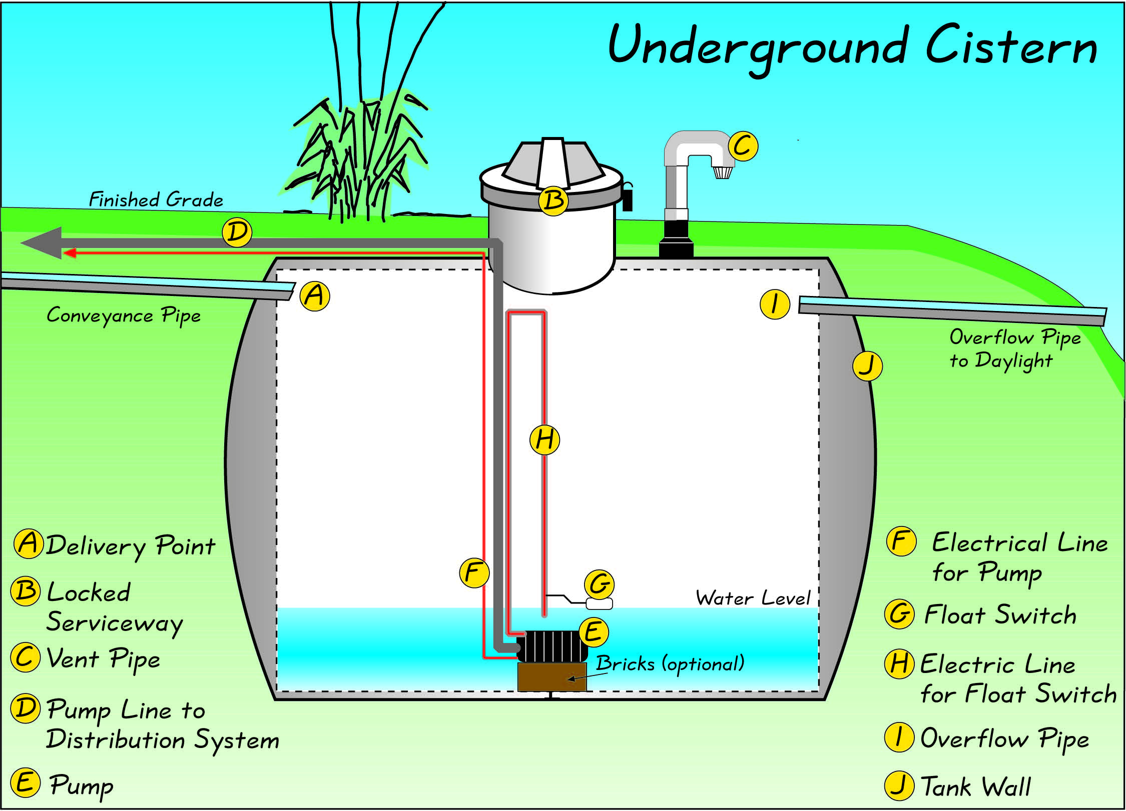
The core of a cistern system is a water-storage tank with a water delivery point, a properly sized overflow pipe, an accessible serviceway (remaining locked when not in use), a working vent, an operational water-pump line, pump and tank walls. Optional items include electric lines, a float switch, in-tank filters, a level reader line, an auxiliary water line, and a ladder, rope or cable (for accessing some of the components). The delivery point (labeled point A in the figure below) is the place where roof water enters the tank. It is located near the top of the tank.
The serviceway (B), also known as the “access way” or “manhole” is needed for cistern maintenance, including servicing the pump, float switch(es), level reader, vent pipe, water lines and electrical lines. The above-grade serviceway opening should remain locked when not in use for safety reasons.
The vent pipe (C) of the depicted cistern begins to the right of the serviceway. This vent is necessary both for effective pumping and for the effective intake of a high volume of water during extreme events. (Vent pipes should be covered with a finemesh screen to prevent mosquitoes and small animals from entering the system.)
The pump line (D) directs harvested water to the plant material via the distribution system using a pump (E). In the case of a separate inline pump and pump house, the pump line would still direct the flow of water to the pump to be distributed. The one difference is that the line would typically have a foot valve at the bottom of the line in the tank so that the pump outside the tank will remain primed (full of water) during the watering season. In many cases, this foot valve is removed during the colder months to prevent freeze damage.
An electric line (F) is required for a sump pump. The electric line is shown entering the tank near the top left side of the serviceway in the figure below. Use professional electricians licensed with the state of New Mexico for this and all electrical work other than 24-volt (and lower) electrical lines.
Float switches (G) like the one under the serviceway in the figure below, are balloon-like devices that float on the surface of the water in the tank in order to tell a pump to turn on or off. Typically, when the water level in a cistern reaches a certain (low) depth, the float switch drops into the “OFF” position, which turns off the pump. (These are also commonly called “pump down switches.”) A float switch can prevent a pump from burning out when the cistern is empty. Also available are submersible pumps with thermal protection shutoffs, so a float switch is not always needed.
The overflow pipe (I) must be large enough to carry runoff in a “100-year storm,” and it must not be the cause of any soil erosion. Erosion-control treatments such as French drains, swales, riprap and wire gabions are often necessary at such points. It is also important to prevent insects and small animals from getting into the overflow pipe. A swing-check valve (that opens only when water is flowing through it) provides this protection.
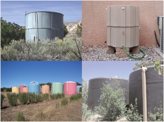
The tank walls (J) come in a variety of shapes and sizes. Tank walls may be constructed out of a variety of materials, many of which are described later in this chapter. Underground tank walls must resist both the inward pressure from the soil and the outward pressure from the stored water. Aboveground tank walls should be dark colored, opaque and UV resistant in order to prevent algae growth that is associated with sunlight exposure.
A level reader (not shown) can be as primitive as a stick with units of measurement etched on the side. The stick is lowered carefully to the tank bottom to determine the height of the water. If you are familiar with the dimensions of your tank, knowing the depth of the water should be enough to give you a ballpark figure of how much water is in storage. Inexpensive level readers, which provide a digital readout of the percentage of water in your cistern, are also available.
If a cistern is empty, manually adding auxiliary water with a hose or via a manual valve may be the only way to use the installed water-deliverysystem to irrigate the landscape. An auxiliary water source can be used when the cistern system is not associated with a strict water budget and when the goal is something less than total roof reliance. However, because the focus of this manual is roofreliant landscaping, the use of an auxiliary water source is not emphasized in this manual nor is it endorsed by the New Mexico Office of the State Engineer. A better option is to provide a secondary water source that can hook directly into your distribution system. This leaves the cistern available for the next precipitation event.
02/08/2016 | (0) Comments


Comments